
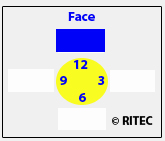
| Face 12: | mils |
|---|---|
| Face 3: | mils |
| Face 6: | mils |
| Face 9: | mils |
| Rim 12: | mils |
|---|---|
| Rim 3: | mils |
| Rim 6: | mils |
| Rim 9: | mils |
| Angular Misalignment Vertical (degrees): | |
|---|---|
| Angular Misalignment Vertical | GAP (Mils/Inch): | |
| Angular Misalignment Horizontal (degrees): | |
| Angular Misalignment Horizontal | GAP (Mils/Inch): |
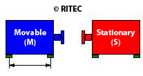
| Vertical Inboard Feet (Movable): | mils |
|---|---|
| Vertical Outboard Feet (Movable): | mils |
| Horiztonal Inboard Feet (Movable): | mils |
| Horizontal Outboard Feet (Movable): | mils |
| Vertical Inboard Feet (Stationary): | mils |
| Vertical Outboard Feet (Stationary): | mils |
| Horiztonal Inboard Feet (Stationary): | mils |
| Horizontal Outboard Feet (Stationary): | mils |
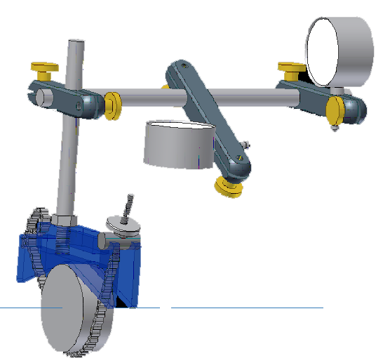
One method of aligning machine shafts is through the use of the Face & Rim Dial Indicator, whereby, by obtaining TIR readings in the Horiztonal & Vertical Planes, machine feet movements to reach the desired alignment tolerances is obtained either graphically or numerically.
Simply enter the required Machine Dimensions, and Dial Guage Indicator Readings, then click the Generate Machine Movements and the Plot Shaft Centerlines Buttons to calculate the required machine movements, and generate the alignment movements graph, respectively.
Please be mindful of the measurements and dimensions units. Two options are presently available; either English Imperial Units: in Thou and inches, or SI Units in mm and cm. Go to the SI Units (mm/cm) Calculator Here
Please Sign-In or Sign-Up using the buttons below.